
The team demonstrated exceptional flexibility, efficiently transitioning from conceptualization to the creation of manufacturable designs. The collaborative effort extended to engaging with factory contacts, ensuring seamless production processes.

Our business-centric product development approach is designed to put your market expertise and industry needs first, creating tailored solutions that drive real-world results. With our experience in technology, healthcare, automotive, consumer goods, etc, we’re committed to helping you lead your industry with innovative, market-responsive products.

Let’s speak about your project for 30-60 minutes and you will discover how our team can help you!
Our business-centric product development approach is designed to put your market expertise and industry needs first.


Emergnt Design Labs excels in rapid, innovative custom product development across various industries, ensuring top-notch design, functionality, and compliance, empowering clients to thrive in their markets.

We turn ideas into products with efficient mechanical engineering and design services. From concept to production, our team ensures timely and reliable solutions.

Reverse engineering is a valuable method for creating custom products, reducing risks, speeding up development, and cutting costs. It empowers businesses to improve existing products, customize offerings, and gain control over their product lines, driving growth and success.

Emergnt Design Labs delivers quick, customized electronic product development services while ensuring compliance with international standards. With expertise in various areas like electronics design, PCB layout, and embedded software, they provide efficient solutions tailored to your needs.

Emergnt Design Labs specializes in developing custom medical devices for various healthcare applications, including diagnostic tools, wearables, mobility aids, prosthetics, and devices for physical rehabilitation specialists. We focus on advancing healthcare through innovative solutions to ensure the best possible patient car


Emergnt Design Labs turns your business challenges into market-ready products. Our diverse team, spanning design and engineering, tackles any project seamlessly. We excel at combining your market insights with our technical expertise, crafting innovative solutions perfectly tailored to your customer needs.

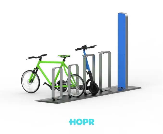
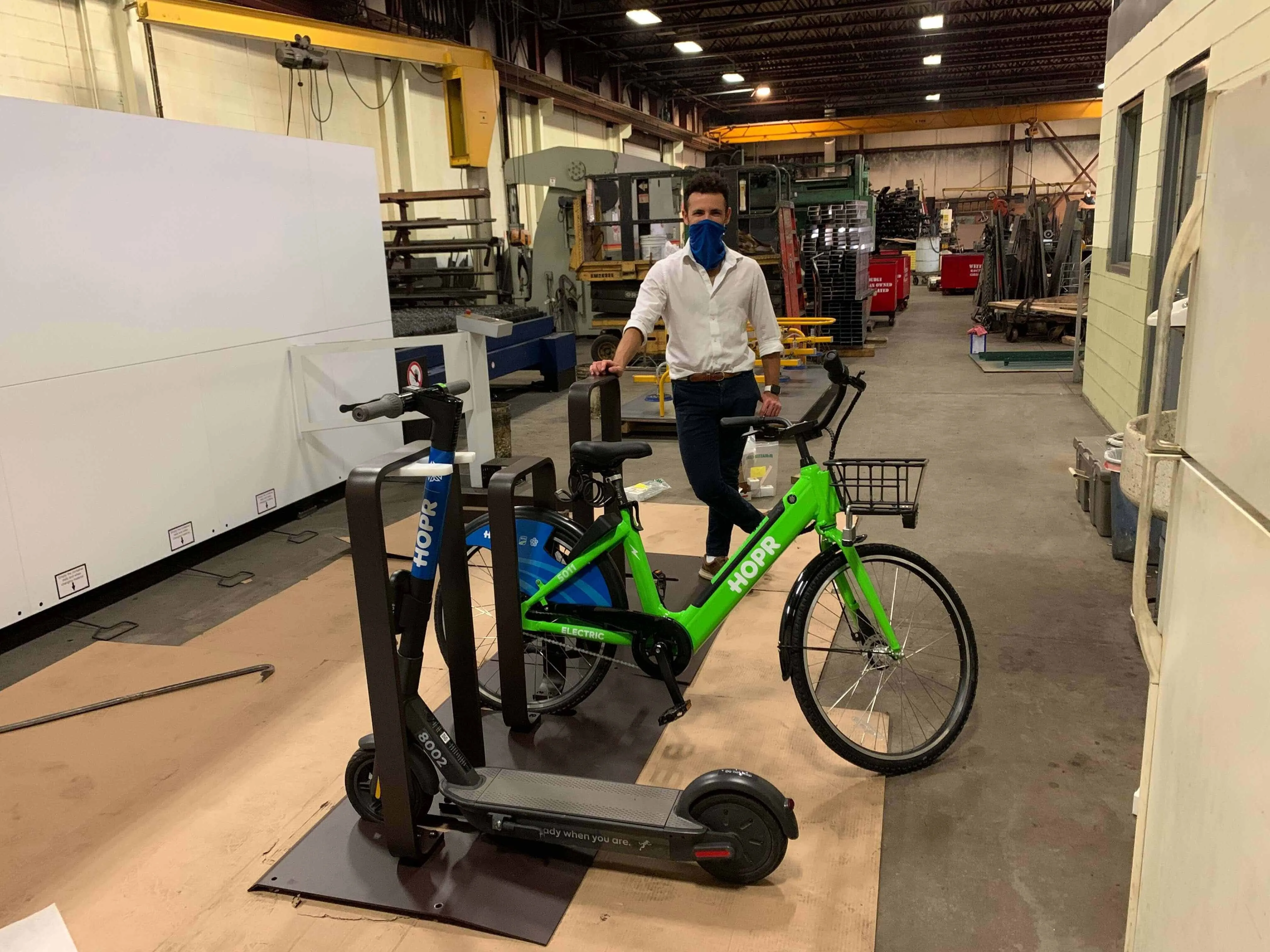
Large or small, we have the flexibility and resources to meet your project needs efficiently. This adaptability is proven by projects like the Hopper Micro Mobility Operator, where we delivered outstanding results quickly and skillfully.

We're committed to innovation and exceeding expectations. By choosing Emergnt, you gain a passionate partner dedicated to bringing your visionary ideas to life and setting new product development benchmarks.
70% of our clients come back for another project. Hear their direct feedback about their project experience.
The team demonstrated exceptional flexibility, efficiently transitioning from conceptualization to the creation of manufacturable designs. The collaborative effort extended to engaging with factory contacts, ensuring seamless production processes.
They met all the challenges along the way, and the result is a great example of how design and function can live in harmony.

The most impressive thing about this company is their ability to rapidly iterate product changes as well as create a seamless production package that I am able to send straight to the factory without having to try to translate it all.